

welcome to my physics blog!
loving you always
scroll down for my profile! :D
Thus far in this unit, our focus has been the reflection of light off flat surfaces and the formation of images by  reflection off of plane mirrors. In Lessons 3 and 4 we will turn attention to the topic of curved mirrors, and specifically curved mirrors which have the shape of spheres. Such mirrors are called spherical mirrors. The two types of spherical mirrors are shown in the diagram on the right. Spherical mirrors can be thought of as a portion of a sphere which was sliced away and then silvered on one of the sides to form a reflecting surface. Concave mirrors were silvered on the inside of the sphere and convex mirrors were silvered on the outside of the sphere. In Lesson 3 we will focus on concave mirrors and in Lesson 4 we will focus on convex mirrors.
Beginning a study of spherical mirrors demands that you first become acquainted with some terminology which will be periodically used. The internalized understanding of the following terms will be essential during Lessons 3 and 4.
| | | |
| | | |
If a concave mirror is thought of as being a slice of a sphere, then there would be a line passing through the center of the sphere and attaching to the mirror in the exact center of the mirror. This line is known as the principal axis. The point in the center of sphere from which the mirror was sliced is known as the center of curvature and is denoted by the letter C in the diagram below. The point on the mirror's surface where the principal axis meets the mirror is known as the vertex and is denoted by the letter A in the diagram below. The vertex is the geometric center of the mirror. Midway between the vertex and the center of curvature is a point known as the focal point; the focal point is denoted by the letter F in the diagram below. The distance from the vertex to the center of curvature is known as the radius of curvature (abbreviated by "R"). The radius of curvature is the radius of the sphere from which the mirror was cut. Finally, the distance from the mirror to the focal point is known as the focal length (abbreviated by "f"). Since the focal point is the midpoint of the line segment adjoining the vertex and the center of curvature, the focal length would be one-half the radius of curvature.
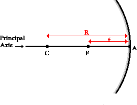
The focal point is the point in space at which light incident towards the mirror and traveling parallel to the principal axis will meet after reflection.  The diagram at the right depicts this principle. In fact, if some light from the Sun was collected by a concave mirror, then it would converge at the focal point. Because the Sun is such a large distance from the Earth, any light rays from the Sun which strike the mirror will essentially be traveling parallel to the principal axis. As such, this light should reflect through the focal point. Perhaps you remember the outdoors demonstration in which a pencil was engulfed in flames in a matter of seconds when placed at the focal point of the demonstration mirror. In the demonstration, whatever light from the Sun which hit the mirror was focused at the point where the pencil was. To the surprise of many, the heat was sufficient to ignite the pencil. Wow!
As we proceed through Lesson 3, we will observe the images formed by concave mirrors. Depending on the object location, the image could be enlarged or reduced in size or even the same size as the object; the image could be inverted or upright; and the image will be located in a specific region along the principal axis. To understand these relationships between object and image, you may need to review these vocabulary terms.
Lesson 3 focused on the reflection of light by concave mirrors and on the formation of images by this reflected light. In that lesson, it was demonstrated that concave mirrors can produce both real and virtual images, depending upon the object location. In Lesson 4, we will follow a similar pattern of inquiry for convex mirrors: investigating how convex mirrors reflect light and produce images; investigating how ray diagrams can be used to estimate image location, size, orientation, and type for objects placed in front of convex mirrors; and using the mirror equation to calculate numerical information about image distance and size if given an object distance, object size and focal length.
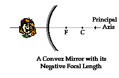 The diagram at the right depicts a convex mirror. In Lesson 3, a convex mirror was described as a portion of a sphere which had been sliced away. If the outside of the sphere is silvered such that it can reflect light, then the mirror is said to be convex. The center of that original sphere is known as the center of curvature (C) and the line which passes from the mirror's surface through the sphere's center is known as the principal axis. The mirror has a focal point (F) which is located along the principal axis, midway between the mirror's surface and the center of curvature. Note that the center of curvature and the focal point are located on the side of the mirror opposite the object - behind the mirror. Since the focal point is located behind the convex mirror, such a mirror is said to have a negative focal length value.
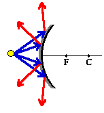 A convex mirror is sometimes referred to as a diverging mirror due to its ability to take light from a point and diverge it. The diagram at the right shows four incident rays emanating from a point and incident towards a convex mirror. These four rays will each reflect according to the law of reflection. After reflection, the light rays diverge; subsequently they will never intersect on the object side of the mirror. For this reason, convex mirrors produce virtual images which are located somewhere behind the mirror.
Throughout this unit on Reflection and the Ray Model of Light, the definition of an image has been given. An image is the location in space where it appears that light diverges from. Any observer from any position who is sighting along a line at the image location will view the object as a result of reflected light; each observer sees the image in the same location regardless of the observer's location. As the observer sights along a line, a ray of light is reflecting off the mirror to the observer's eye. Thus, the task of determining the image location of an object is to determine the location where reflected light intersects. The diagram below shows an object placed in front of a convex mirror. Several rays of light emanating from the object are shown approaching the mirror and subsequently reflecting. Each observer must sight along the line of the reflected ray to view the image of the object. Each ray is extended backwards to a point of intersection - this point of intersection of all extended reflected rays indicates the image location of the object.
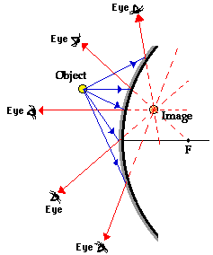
The image in the diagram above is a virtual image. Light does not actually pass through the image location. It only appears to observers as though all the reflected light from each part of the object is diverging from this virtual image location. The fact that all the reflected light from the object appears to diverge from this location in space means that any observer would view a replica or reproduction when sighting along a line at this location.
Of course to determine the image location, only a pair of incident and reflected rays need to be drawn. It is customary to select the pair of rays which are easiest to draw. Of the five pairs of incident and reflected rays in the diagram above, two correspond to the rays which are customarily drawn. In fact, they may closely resemble the two rays which were used in concave mirror ray diagrams. Recall from Lesson 3 that there were two rules of reflection for concave mirrors. They are:
The revised rules can be stated as follows:
In the diagram above, the second and third (from the top) blue incident ray exemplify these two rules of reflection for convex mirrors. Using this pair of incident and reflected rays will greatly simplify the task of drawing ray diagrams and determining the location of images. In the next section of this Lesson, such ray diagrams will be shown.
Human eyes have often been compared to cameras. They are alike in terms of structure, but they have one fundamental difference in functioning mechanism.
| Function | Camera | Human Eye | |
|---|---|---|---|
 | |||
| Similarities | |||
| 1. | opening for light to enter | aperture | pupil |
| 2. | control the amount of light entering camera/eye | diaphragm control size of aperture | iris muscles control size of pupil |
| 3. | refract light | glass biconvex lens | mainly cornea ; lens, aqueous & vitreous humor |
| 4. | object of light action to form image | photosensitive chemicals on film | photoreceptors(rods & cones) in retina |
| 5. | absorb excessive light to prevent multiple images formation | dark internal surface | pigmented, dark choroid |
| Difference | |||
| 1. | focusing mechanism | change distance between lens & film | change focal length of lens using ciliary muscles |
An optical fiber (or fibre) is a glass or plastic fiber designed to guide light along its length by confining as much light as possible in a propagating form. In fibers with large core diameter, the confinement is based on total internal reflection. In smaller diameter core fibers, (widely used for most communication links longer than 200 meters) the confinement relies on establishing a waveguide. Fiber optics is the overlap of applied science and engineering concerned with such optical fibers. Optical fibers are widely used in fiber-optic communication, which permits transmission over longer distances and at higher data rates than other forms of wired and wireless communications. They are also used to form sensors, and in a variety of other applications.
The term optical fiber covers a range of different designs including graded-index optical fibers, step-index optical fibers, birefringent polarization-maintaining fibers and more recently photonic crystal fibers, with the design and the wavelength of the light propagating in the fiber dictating whether or not it will be multi-mode optical fiber or single-mode optical fiber. Because of the mechanical properties of the more common glass optical fibers, special methods of splicing fibers and of connecting them to other equipment are needed. Manufacture of optical fibers is based on partially melting a chemically doped preform and pulling the flowing material on a draw tower. Fibers are built into different kinds of cables depending on how they will be used.
Light is known to behave in a very predictable manner. If a ray of light could be observed approaching and reflecting off of a flat mirror, then the behavior of the light as it reflects would follow a predictable law known as the law of reflection. The diagram below illustrates the law of reflection.

In the diagram, the ray of light approaching the mirror is known as the incident ray (labeled I in the diagram). The ray of light which leaves the mirror is known as the reflected ray (labeled R in the diagram). At the point of incidence where the ray strikes the mirror, a line can be drawn perpendicular to the surface of the mirror; this line is known as a normal line (labeled N in the diagram). The normal line divides the angle between the incident ray and the reflected ray into two equal angles. The angle between the incident ray and the normal is known as the angle of incidence. The angle between the reflected ray and the normal is known as the angle of reflection. (These two angles are labeled with the Greek letter "theta" accompanied by a subscript; read as "theta-i" for angle of incidence and "theta-r" for angle of reflection.) The law of reflection states that when a ray of light reflects off a surface, the angle of incidence is equal to the angle of reflection.
It is likely that you observed the law of reflection at work in the Images, Images, Images Lab. As discussed in the previous section of Lesson 1, to view an image of a pencil in a mirror, you must sight along a line at the image location. As you sight at the image, light travels to your eye along the path shown in the diagram below. The diagram shows that the light reflects off the mirror in such a manner that the angle of incidence is equal to the angle of reflection.

It just so happens that the light which travels along the line of sight to your eye follows the law of reflection. (The reason for this will be discussed later in Lesson 2). If you were to sight along a line at a different location than the image location, it would be impossible for a ray of light to come from the object, reflect off the mirror according to the law of reflection, and subsequently travel to your eye. Only when you sight at the image, does light from the object reflect off the mirror in accordance to the law of reflection and travel to your eye. This truth is depicted in the diagram below.

For example, in Diagram A above, the eye is sighting along a line at a position above the actual image location. For light from the object to reflect off the mirror and travel to the eye, the light would have to reflect in such a way that the angle of incidence is less than the angle of reflection. In Diagram B above, the eye is sighting along a line at a position below the actual image location. In this case, for light from the object to reflect off the mirror and travel to the eye, the light would have to reflect in such a way that the angle of incidence is more than the angle of reflection. Neither of these cases would follow the law of reflection. In fact, in each case, the image is not seen when sighting along the indicated line of sight. It is because of the law of reflection that an eye must sight at the image location in order to see the image of an object in a mirror.
SOHCAHTOA
A way of remembering how to compute the sine, cosine, and tangent of an angle.
SOH stands for Sine equals Opposite over Hypotenuse.
CAH stands for Cosine equals Adjacent over Hypotenuse.
TOA stands for Tangent equals Opposite over Adjacent.

| Example: | Find the values of |  |
| Answer: | sin θ = 3/5 = 0.6 cosθ = 4/5 = 0.8 tanθ = 3/4 = 0.75 |  |
This triangle is oriented differently than the one shown in the SOHCAHTOA diagram, so make sure you know which sides are the opposite, adjacent, and hypotenuse. | ||
Just as distance and displacement have distinctly different meanings (despite their similarities), so do speed and velocity. Speed is a scalar quantity which refers to "how fast an object is moving." A fast-moving object has a high speed while a slow-moving object has a low speed. An object with no movement at all has a zero speed.
Velocity is a vector quantity which refers to "the rate at which an object changes its position." Imagine a person moving rapidly - one step forward and one step back - always returning to the original starting position. While this might result in a frenzy of activity, it would result in a zero velocity. Because the person always returns to the original position, the motion would never result in a change in position. Since velocity is defined as the rate at which the position changes, this motion results in zero velocity. If a person in motion wishes to maximize their velocity, then that person must make every effort to maximize the amount that they are displaced from their original position. Every step must go into moving that person further from where he/she started. For certain, the person should never change directions and begin to return to where he/she started from.
Velocity is a vector quantity. As such, velocity is "direction-aware." When evaluating the velocity of an object, one must keep track of direction. It would not be enough to say that an object has a velocity of 55 mi/hr. One must include direction information in order to fully describe the velocity of the object. For instance, you must describe an object's velocity as being 55 mi/hr, east. This is one of the essential differences between speed and velocity. Speed is a scalar and does not keep track of direction; velocity is a vector and is direction-aware.
 The task of describing the direction of the velocity vector is easy! The direction of the velocity vector is simply the same as the direction which an object is moving. It would not matter whether the object is speeding up or slowing down, if the object is moving rightwards, then its velocity is described as being rightwards. If an object is moving downwards, then its velocity is described as being downwards. So an airplane moving towards the west with a speed of 300 mi/hr has a velocity of 300 mi/hr, west. Note that speed has no direction (it is a scalar) and velocity is simply the speed with a direction.
As an object moves, it often undergoes changes in speed. For example, during an average trip to school, there are many changes in speed. Rather than the speed-o-meter maintaining a steady reading, the needle constantly moves up and down to reflect the stopping and starting and the accelerating and decelerating. One instant, the car may be moving at 50 mi/hr and another instant, it might be stopped (i.e., 0 mi/hr). Yet during the course of the trip to school the person might average 25 mi/hr.